
























The core principles of CNC machine tool installation preparation: follow the manufacturer’s installation manual and foundation drawing; plan before construction; coarse before fine; mechanical before electrical; no-load before load.
At Grand CNC, we strive to make the process of delivering and installing your new machine tool expedient, accurate and easy for our customers. To that end, here are some CNC Machine Tool Installation Preparation tips to make the process as seamless as possible.
Obtain documentation first: Request the foundation drawing, lifting diagram, electrical wiring diagram, air supply/hydraulic requirements, total weight, center of gravity, and anchor bolt specifications from the manufacturer in advance.
Verify the site: Door width, passageways, ceiling height, floor load-bearing capacity, lifting equipment capacity, power supply capacity, air supply pressure, chip removal and maintenance space.
Environmental requirements: Keep the machine as far as possible from vibration sources such as punch presses, forging hammers, and frequent overhead crane impacts. For precision machine tools, constant temperature, dustproofing, moisture protection, and a corrosion-free gas environment are recommended. Avoid direct sunlight and local heat sources.
Plan the layout: Position the machine according to the floor plan, leaving space for operation, maintenance, lifting, and chip removal. Generally, sufficient distance must be left between the machine and walls or columns.
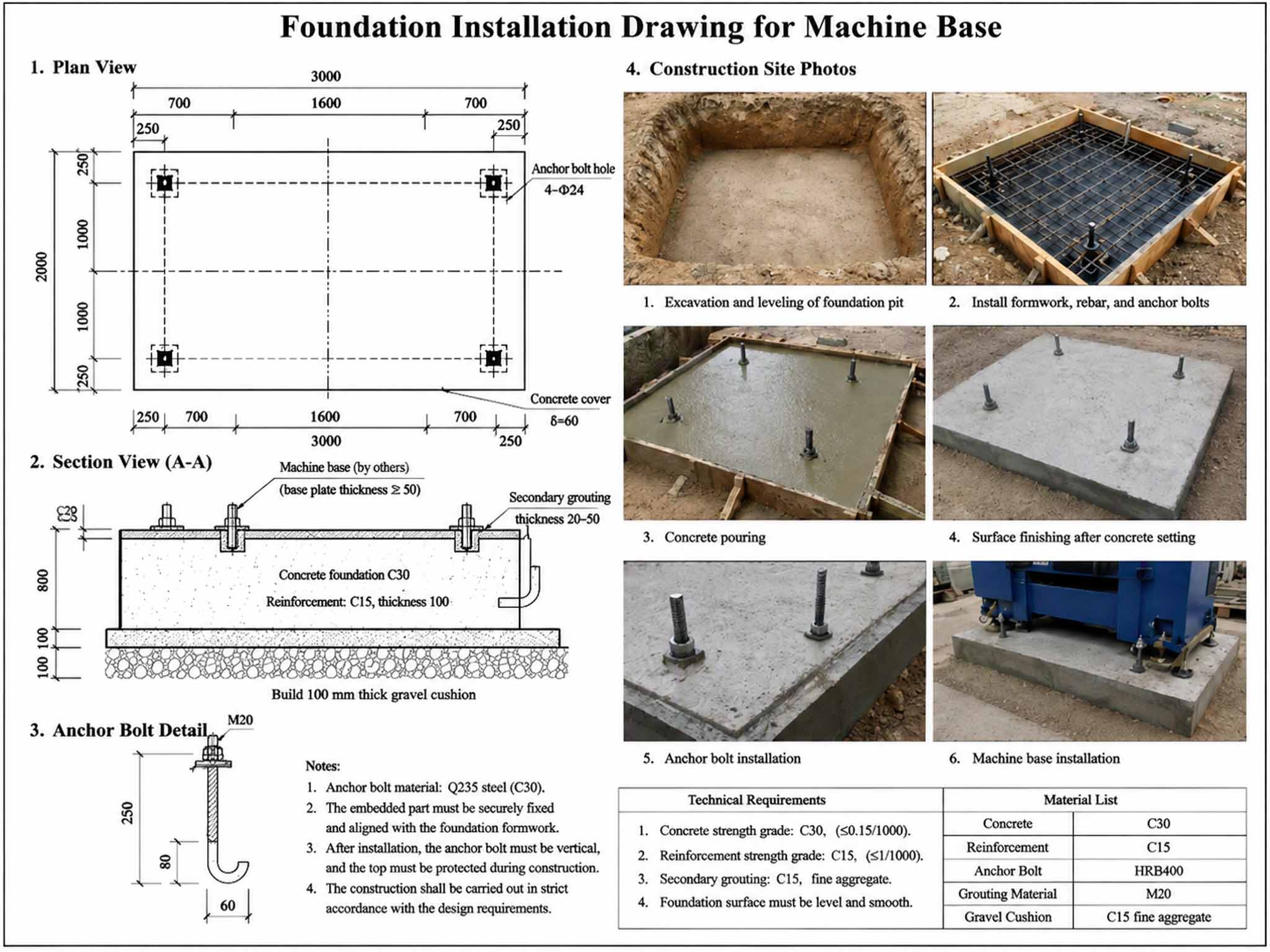
Strictly follow the foundation drawing: The foundation concrete strength, dimensions, reserved hole positions, and depth must meet the manufacturer’s requirements. Install only after curing has reached the required strength.
Protect reserved holes: Seal them with wooden molds or foam during pouring to prevent debris from entering. Clean them thoroughly and wet the hole walls before grouting.
Leveling pad/shim techniques: Place leveling pads on both sides of anchor bolts and appropriately increase their density under guideways. Use wedge shims in pairs with sufficient overlap. Do not use too many shims per group, generally no more than 3–5 pieces. The shims must make good contact with the foundation, not just point contact.
Secondary grouting: Use high-strength, non-shrink grout, and ensure the grouting layer is dense. After it reaches strength, perform fine adjustment and locking.
Unpacking inspection: Check whether the packaging is damaged, count the main machine, accessories, and accompanying documents according to the packing list, take photos as evidence, and report problems promptly.
Lifting safety: Strictly use the lifting points marked by the manufacturer. Do not lift the spindle, ball screws, guards, or other precision parts. Use lifting straps to protect the painted surfaces. Perform a trial lift of 100–200 mm off the ground to check balance.
Transport fixation: Before moving, lock moving parts such as the table, spindle, tool magazine, and tailstock. After arrival, remove shipping braces, supports, and tie straps one by one according to the list.
Prevent impact: Move slowly and avoid tilting, dropping, or collision, especially for precision guideways and the spindle.
Rough positioning: Position according to the layout drawing, align the anchor bolts with the holes, and initially adjust the leveling pads so that the machine is basically level.
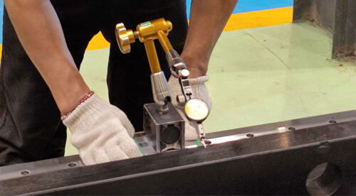
Use of precision levels: Use a 0.02 mm/m or higher-precision level and measure in both longitudinal and transverse directions. For large machines, measure both ends and the middle of the guideways.
Adjustment sequence: First adjust the bed level, then the column, spindle, and table. Coarse adjustment before fine adjustment; adjust diagonally, and measure repeatedly.
Re-measure after locking: Level will change after the anchor bolts are tightened, so re-measurement is mandatory. If necessary, perform fine adjustment again after secondary grouting.
Prevent distortion: Multiple leveling pads must bear load evenly. Avoid forced tightening that causes bed deformation.
Power supply: Confirm voltage, frequency, capacity, and phase sequence. Incorrect phase sequence will cause the spindle to rotate in reverse and the oil pump to run backward. Grounding must follow the manufacturer’s requirements; usually the grounding resistance should be ≤4 Ω. A voltage stabilizer or isolation transformer is recommended.
Air supply: Ensure dry, clean, and stable pressure. Add a refrigerated air dryer and filter to prevent moisture and oil from entering the air circuit.
Hydraulic/lubrication: Fill with the oil grade specified by the manufacturer. Filter the oil before filling. Check oil level, oil lines, and seals. Clean off anti-rust oil and check lubrication lines.
Cooling and chip removal: Confirm the positions and flow directions of the coolant, chip conveyor, and coolant tank to avoid water and oil leakage.
Before commissioning: Check wiring, insulation, and phase sequence. Manually bar over or jog the motor to confirm rotation direction. Check limits, emergency stop, homing, and alarms.
Parameter backup: Back up NC parameters, PLC data, and tool magazine data. Record the original settings.
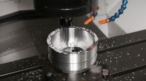
Accuracy inspection: Geometric accuracy, positioning accuracy, and repeat positioning accuracy. Use a laser interferometer or ballbar if necessary. Machine test workpieces such as circles, squares, and slots, and check surface quality and dimensions.
Records and signatures: Keep installation logs, level data, accuracy reports, and photos for future maintenance and claims.
In one sentence: Spending more time during the installation preparation stage verifying documentation, the foundation, and utilities will save a great deal of time during later commissioning. Specific operations are subject to the manufacturer’s installation manual and engineer guidance.
 Industry
 Products
 Products
 Products
 Products
 Products

English

French

Portuguese

Spanish