

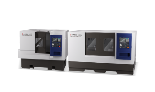
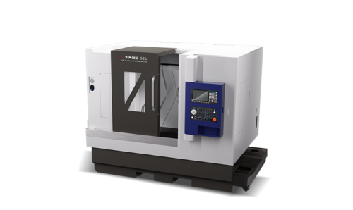
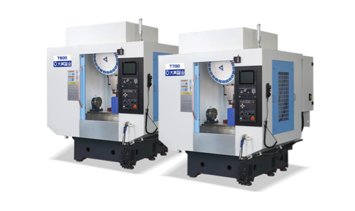
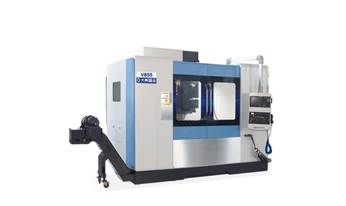







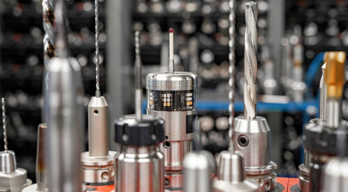

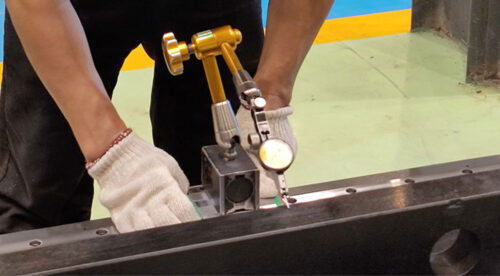

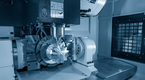
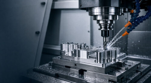

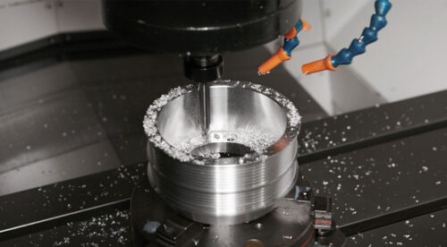

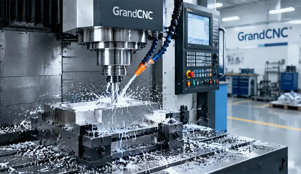
Milling sits among the core manufacturing machining processes alongside turning. Shops rely on milling to drill holes, machine flat planes and cut grooves. Multiple machine variants from manual universal mills to full‑featured machining centers support this work, paired with a broad selection of cutting tools. In this GrandCNC blog post, we walk you through milling machines, operational workflows, cutter types and practical production guidance.
Milling uses high‑speed rotary cutters to chip away material from raw workpieces. First, we cover its core operating principles.
Milling works when spinning cutting tools engage your secured workpiece. Industry experts name milling “interrupted cutting”, since cutter teeth repeatedly make and lose contact with material during rotation.
You can produce square, round, box‑style and many custom part shapes through plane cutting, grooving and other routines. Machines equipped with multi‑axis drive systems even manufacture complex 3‑dimensional components.
Next, we clarify milling versus turning differences. Turning mounts workpieces onto a spinning spindle and uses stationary cutters. It excels for cylindrical parts and internal bore machining.
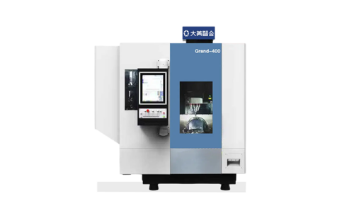
For quick reference, broad “machining” refers to work completed by machining centers. These platforms build upon NC milling machines and add NC control plus automatic tool changers. So milling forms the foundational base for machining‑center workflows.
Early manual milling devices appeared in the 19th‑century industrial age. Workers operated these machines fully by hand, and human skill determined final part quality.
Next, numerical‑control technology emerged in the mid‑20th century. NC‑driven milling replaced manual hand‑crank adjustment with coded program commands. This change drastically boosted repeatability for batch production.
Then CAD/CAM software arrived in the 1970s‑80s. Programmers generate complex tool paths digitally instead of writing code manually. Soon after, automatic tool changers became mainstream on machining centers.
Today, GrandCNC and other equipment builders integrate smart monitoring, high‑speed spindles and multi‑axis functions. Modern milling machines support prototyping, low‑mix high‑volume and high‑mix low‑volume manufacturing scenarios.
Every milling machine shares standard hardware assemblies that jointly deliver precise metal removal. Below we break down each critical part.
The spindle drives and clamps cutting tools. It delivers controlled rotary speed to complete chip removal. Spindle rigidity directly impacts surface finish and tool service life.
Worktable / Workholding Fixtures firmly fasten your raw workpiece stock. Good fixtures eliminate shifting during heavy cuts and guarantee consistent dimensional output.
Automatic Tool Changer (ATC) equips most modern machining centers. It swaps cutters automatically without manual intervention, and it cuts down non‑productive setup time.
CNC Controller reads G‑code programs and sends motion commands to drive motors. Operators set cutting speeds, feed rates and axis movements through this unit.
Coolant & Chip Removal System dissipates cutting heat, lubricates cutting edges and flushes metal chips away from the machining zone. It protects both tools and finished workpiece surfaces.
Axis Drive Assembly executes X‑Y‑Z linear movements; advanced machines add rotary A/B/C axes for multi‑side and curved‑surface jobs.
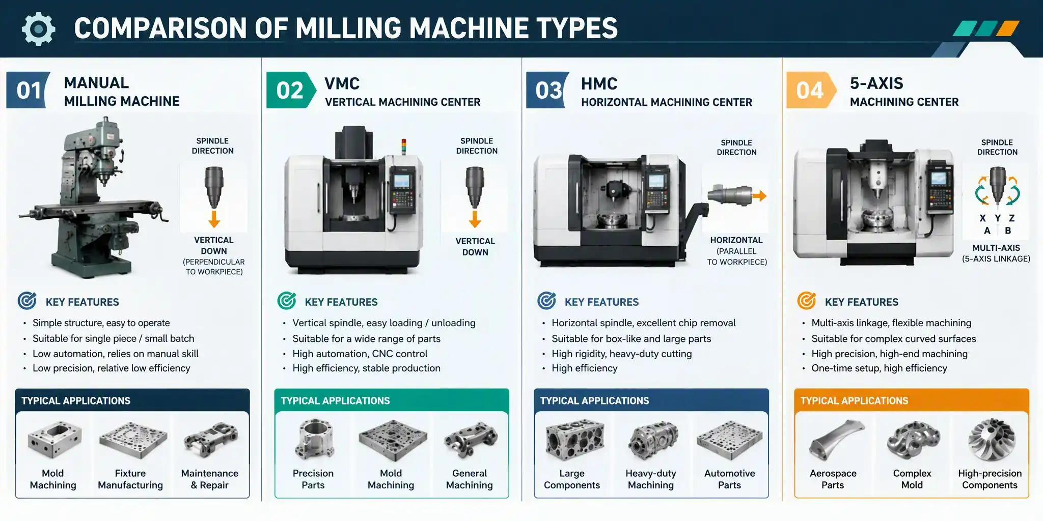
You select machine types based on lot size, part geometry and accuracy targets. GrandCNC supplies multiple milling platforms for different production needs.
Manual Universal Milling Machine relies on manual handwheel adjustment. Skilled operators control every tool movement. These low‑cost machines fit small‑batch prototypes and simple repair work. Human experience heavily influences final machining quality.
NC / CNC Milling Machine follows pre‑written digital programs. It removes manual adjustment errors. You deploy these machines for repeated, accurate runs for mid‑to‑large‑batch orders.
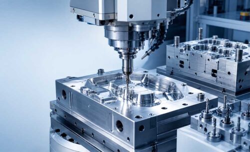
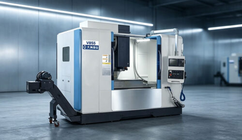
Vertical Machining Center (VMC) features a vertically‑oriented spindle. It works great for plate‑type parts, mold cavities and general‑purpose component production. Most job shops adopt vertical machining centers as standard equipment.
Horizontal Machining Center (HMC) holds a horizontal spindle. It excels at heavy‑duty cutting and multi‑face machining. Mass‑production automotive and hydraulic component plants widely use horizontal models.
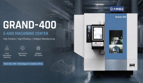
5‑Axis Machining Center controls three linear plus two rotary axes simultaneously. It completes complex curved aerospace, medical or mold parts in a single clamping setup. It reduces repeated re‑mounting errors significantly.
Special‑Purpose Gear Milling Machine focuses exclusively on gear tooth generation. Program input defines tooth count, modulus and tolerance for high‑precision gear mass manufacturing.
Tool selection directly decides machining efficiency and finished quality. Match your cutter choice to workpiece material and target geometry.
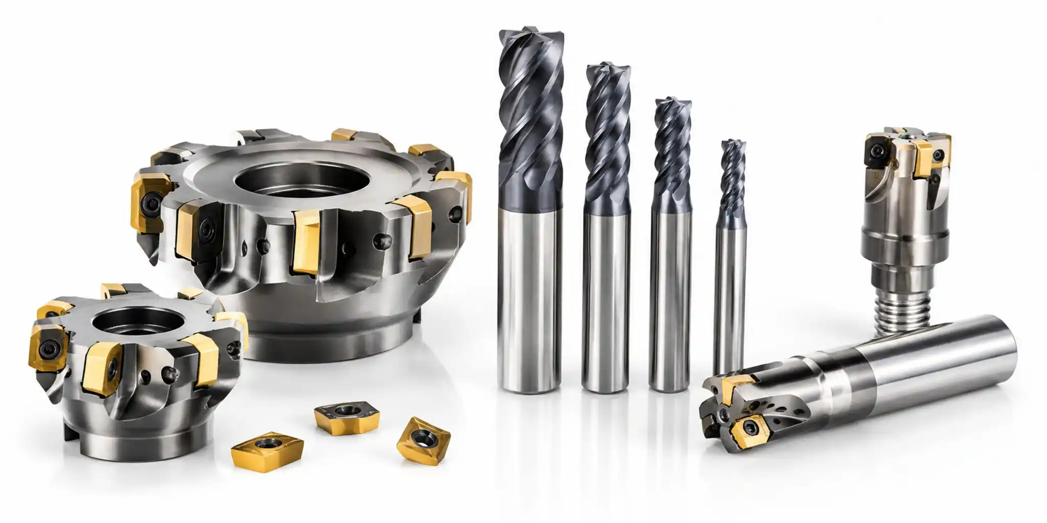
Face Mill carries multiple indexable inserts. It machines large flat reference surfaces fast. Shops use face mills for squaring raw stock blanks.
End Mill features cutting edges on both end face and peripheral sides. It handles slotting, side profiling, pocketing and fine detailed features. End mills exist in countless sizes and coating grades.
Groove / Slot Mill carries disc‑shaped cutting edges. It produces T‑slots, dovetail grooves and special recess profiles that standard end mills cannot easily achieve.
Flat Milling Cutter mounts for horizontal milling setups. It removes material across broad flat zones and delivers consistent flatness for large workpieces.
Special‑form cutters also exist. You deploy these custom tools for non‑standard profiles to lower total machining cycle time.
You tune these core cutting parameters before running any milling job. Wrong settings accelerate tool wear or ruin part accuracy.
Cutting Speed defines surface velocity between cutter edge and workpiece. You calculate cutting speed with the formula V (m/min) = π × D × N / 1000. Adjust values for workpiece material and tool substrate grade.
Cutting Depth & Cutting Width control how much material you remove in each pass. Larger depths speed up roughing operations, yet they raise cutting force and heat buildup.
Feed Rate describes table travel speed. The formula F (mm/min) = f × z × N calculates table feed, where f stands for feed‑per‑tooth, z for flute count and N for spindle RPM.
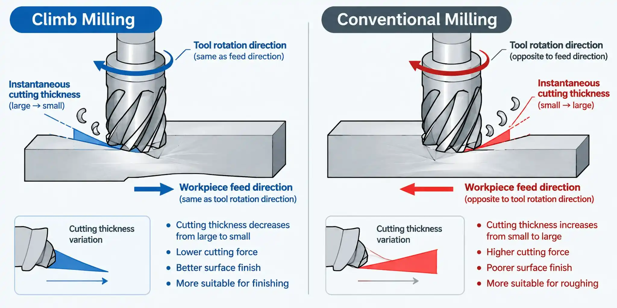
Climb Milling (Downcut) vs Conventional Milling (Upcut) represents two core cutting modes. Climb milling matches tool rotation direction to table feed direction; it delivers longer tool life and less vibration. Most modern CNC machining centers prioritize climb milling for general‑purpose work. Conventional milling suits hard, scaled raw cast material.
Milling supports diverse feature‑making tasks for prismatic mechanical components.
Face Milling / Plane Cutting creates flat reference planes and trims raw blanks down to target thickness. Every mechanical assembly requires precisely milled reference surfaces.
Side Milling machines outer part contours and adjusts workpiece length or width dimensions. End mills perform most side‑milling tasks.
Step Milling generates offset stepped surfaces with sharp or radiused internal corners. Programmers add corner‑R or corner‑C chamfer cycles to match drawing specifications.
Groove & Slot Machining produces T‑slots, dovetail slots and standard open slots. You combine end mills and dedicated groove cutters for these features.
Hole‑Making Milling Workflows cover hole drilling, tapping for internal threads, reaming for smooth hole walls and counter‑boring for bolt‑head recesses. Machining centers finish all these hole operations in one setup.
3D Contour Milling uses simultaneous multi‑axis movement. It produces free‑form curved surfaces typical for molds, turbine parts and custom tooling, usually paired with CAD/CAM programming systems.
Below we list typical milling use‑cases you will encounter in daily manufacturing.
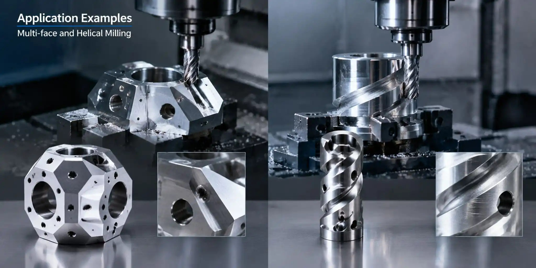
Multi‑Face Machining: You machine four, five or six sides of one workpiece. Manual mills demand repeated part re‑clamping. Machining centers finish multi‑face jobs in one fixture setup and cut down alignment errors.
Hexagon Feature Machining: This process forms hexagonal outer profiles for nuts, bolt heads and fastening hardware.
Helical Milling: The tool follows spiral tool paths across X‑Y‑Z axes. Manufacturers use helical interpolation for thread milling and circular hole ramping.
Undercut Machining: Operators add corner relief cutouts. This technique eliminates unwanted leftover arc radii in sharp internal corners when tool geometry cannot physically reach a perfect sharp angle.
First, milling delivers reliable high‑precision output. CNC‑controlled milling centers maintain tight dimensional tolerances and keep part‑to‑part variation minimal across batches.
Second, milling offers outstanding geometric flexibility. One machine handles flats, slots, holes, steps and complex curved profiles. Multi‑axis models expand manufacturing possibilities even further.
Third, automated milling workflows save production steps. After you validate a CNC program, the machine runs unattended. ATC tool‑swapping eliminates frequent manual tool‑change downtime.
Fourth, milling adapts well to varied production volumes. It supports one‑off prototypes, small‑batch orders and continuous mass manufacturing.
Milling technology does have inherent limits you must respect during part design and production planning.
Rotating cutters always produce internal corner radii. You cannot achieve mathematically sharp inside corners with standard milling tools. Designers must add corner relief features on drawings.
You must match cutting tools, fixture hardware and cutting parameters to your workpiece material. Improper selections cause excessive tool chipping, workpiece shifting, vibration or even equipment damage. Always verify setup before full‑speed production runs.
Thin‑wall structures risk part deflection under cutting forces. You apply light finishing cuts and optimize clamping schemes to reduce workpiece distortion.
Many job‑shop owners struggle to match machine performance to their actual production mix. GrandCNC’s engineering team shares practical selection guidance for your investment decision.
First, map your typical workpiece size and weight. Confirm machine‑table travel, load capacity and working envelope can accommodate your largest regular parts.
Second, define your required complexity level. Select 3‑axis vertical centers for standard prismatic components. Choose horizontal machines for heavy‑cut multi‑face mass production. Pick 5‑axis platforms if you regularly produce complex curved parts.
Third, evaluate your production lot profile. Prioritize machines with fast ATC for high‑volume jobs. For prototype‑heavy workshops, focus on machine rigidity and easy‑to‑learn controller interfaces.
Fourth, consider future business growth. GrandCNC engineers help you balance upfront budget against long‑term expandability, spindle‑power options and optional smart monitoring upgrades.
Reach out to GrandCNC’s technical team. Our experts analyze your part drawings and production targets, and they recommend milling‑machine solutions tailored for your workshop.
 Industry
 Products
 Products
 Products
 Products
 Products

English

French

Portuguese

Spanish