







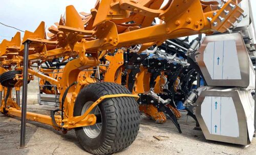



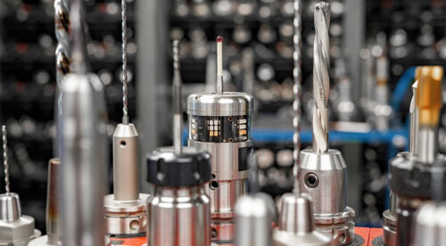










We deliver not just CNC machine tools, but also peace of mind and worry-free service.

Every CNC machine tools made from Grand is produced in strict accordance with the ISO standard. During this process, a variety of quality management tests will be carried out. Our QC process is a rigorous system that spans the entire process of design, procurement, manufacturing, assembly, commissioning, inspection, and delivery, aiming to ensure that every machine tool meets the design specifications for accuracy, performance, and reliability. The specific process is as follows:
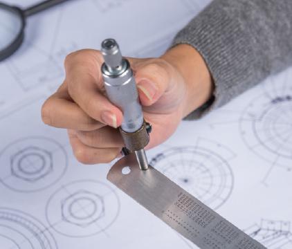
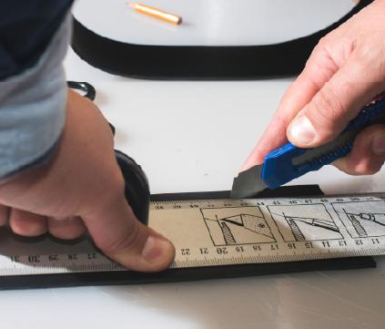
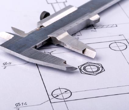

This is the first step in ensuring the basic quality of the machine tool. The specific inspection process is as follows:
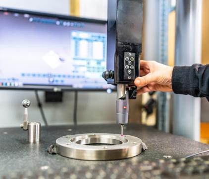
Use a coordinate measuring machine to inspect key geometric dimensions, flatness, straightness, and hole position accuracy. Check the casting quality (for sand holes and cracks).
Conduct dynamic balancing tests, radial/axial runout tests, and temperature rise simulation tests.
Inspect straightness, pitch error, surface finish, and hardness.
Conduct power-on tests and functional tests, and compare the results with the inspection reports provided by the supplier.
Conduct motion tests and positioning accuracy tests.
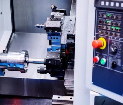

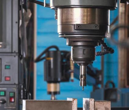
Inspect the level adjustment of the machine bed. Check the quality of the scraping or bonding process of key mating surfaces (such as guide rail mounting surfaces), using the common dye penetration method to check contact points.
Before the installation of the spindle, lead screw, etc., preliminarily adjust the perpendicularity and parallelism of large components such as the machine bed, column, and saddle.
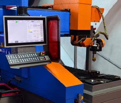
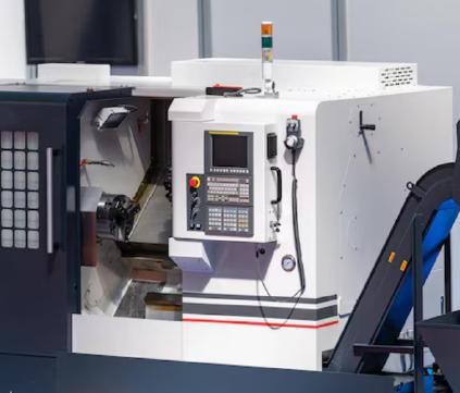
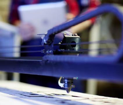
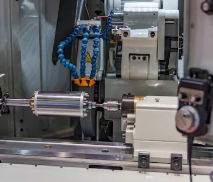
This is the most critical and comprehensive stage of the QC process, usually conducted according to international standards.
Testing the straightness, pitch, yaw, and roll of motion within the effective travel range of the X/Y/Z axes.
Such as the perpendicularity of the X-axis to the Y/Z axes, the perpendicularity of Z-axis movement to the worktable, and the perpendicularity of the spindle axis to the worktable.
Radial runout and axial runout of the spindle end, and radial runout of the spindle taper hole.
The deviation between the actual position reached by the axis and the commanded target position (i.e., "how accurate it is").
The consistency of the axis when repeatedly returning to the same target position (i.e., "how stable it is"), which is key to machine tool stability.
The error caused by screw clearance, etc., when the axis moves in forward and reverse directions.
Linear displacement deviation caused by the manufacturing error of the lead screw itself.
Slight angular deflection of moving parts during travel.
Tests the contour error when two or more axes interpolate a circular path (often tested using a ballbar).
Whether G-codes (preparatory functions), M-codes (miscellaneous functions), S-codes (spindle speed), and T-codes (tool selection) are executed correctly.
The smoothness and accuracy of linear interpolation, circular interpolation, helical interpolation, etc.
Whether pitch error compensation, backlash compensation, and tool radius/length compensation are effective and accurate.
The stepless speed regulation range of the spindle, oriented spindle stop (for tool changes), and rigid tapping function.
Automated testing of the cooling system, chip conveyor system, lubrication system, and pneumatic/hydraulic systems.
The stability of program transfer (DNC), network connection, and data acquisition functions.
Temperature changes in key components (spindle bearings, screw nuts, guideways) after the machine runs at high speed for several hours.
Monitoring changes in spindle elongation and geometric accuracy of each axis under cold and hot states.
Determining the time required for the machine to reach thermal equilibrium, so as to establish a warm-up program in production.
Testing the impact of workshop ambient temperature fluctuations on machine tool accuracy.
The rigidity and anti-vibration capability of the machine under heavy cutting (whether there is chatter).
Whether the surface finish of the machined workpiece meets the requirements.
Checks whether the roundness, cylindricity, flatness, hole spacing, etc., of the test piece are within tolerance.
Tool wear under specific cutting parameters.
Tests the machining capability of complex curved surfaces (such as impellers, molds) and checks for overcut or undercut.
The sensitivity of protective door interlocks, emergency stop buttons, and light curtains/safety light barriers.
Grounding resistance, insulation resistance, and withstand voltage testing.
Overload alarm and protection functions for servo motors and spindle motors.
Simulating various faults (such as insufficient air pressure, low oil level, overtravel) to check whether the system can correctly alarm and shut down.
Evaluating reliability by statistically analyzing the failure rate through long-term continuous operation (running-in testing).
Measuring the noise decibel level and vibration amplitude during machine operation to ensure compliance with environmental and occupational health standards.




After completing all tests, the critical geometric and positional accuracies are re-verified to ensure all data are within the tolerance limits.
The machine tool is thoroughly cleaned, and exposed metal surfaces are treated with rust preventative.
The user manual, electrical diagrams, PLC program, accuracy inspection report, certificate of conformity, and other accompanying documents, as well as the standard tools and spare parts kit, are verified.




The customer inspects the appearance and accessories on-site to ensure they are in good condition.
Installation and leveling are performed according to requirements.
The manufacturer's engineer restores the factory accuracy on-site.
On-site at the customer's location, key accuracy and performance tests are repeated according to the acceptance criteria specified in the contract. The customer signs the acceptance report after confirming satisfactory results.

English

French

Portuguese

Spanish