


















We deliver not just CNC machine tools, but also peace of mind and worry-free service.

The machine home position is the system's initial reference point, which needs to be manually or automatically returned to the home position. The workpiece origin, on the other hand, is a reference point set on the workpiece based on the machining requirements. The tool is moved to the workpiece reference position, and this point is set as the workpiece coordinate origin. Different workpiece origins are typically set using G54 to G59 commands.Steps to exclude
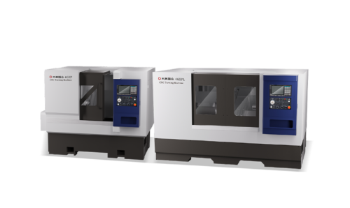
The fundamental difference lies in how the workpiece moves. On a CNC turning machine, the spindle holds and rotates the workpiece while the cutting tool performs the feed motion to execute the cut; conversely, on a CNC milling machine, the tool rotates while the workpiece, clamped to the worktable, moves. Modern CNC turning machines with three or more axes effectively integrate both turning and milling capabilities, typically performing turning operations first, followed by centerline or off-center milling.
Check Your Setup and Workpiece First
Inspect and Maintain the Lathe
Adjust Your Cutting Technique
This is a classic sign of excessive backlash. It is usually caused by a loose or worn setscrew on the leadscrew, creating a gap between the nut and the leadscrew. Solution: Adjust the setscrew on the compound rest leadscrew or the cross-slide leadscrew to keep the backlash within approximately 0.025 mm. If the backlash persists after adjustment, inspect the leadscrew and half-nut for wear and replace them if necessary.
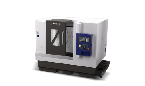
While both are often collectively referred to as "turn-mill" machines, their machining capabilities differ significantly. A lathe with a live-tool turret typically features a milling spindle with only 3–10 HP and lower rigidity; it is prone to chatter when using long tools and often lacks a Y-axis, limiting machining to features aligned with the centerline or on the outer diameter. In contrast, a true turn-mill center is equipped with a dedicated milling spindle (15–30+ HP) and a standard Y-axis; it utilizes taper-shank tool holding, offering far superior rigidity and machining capabilities. When purchasing, be sure to verify the presence of a Y-axis and the milling spindle power.
This is due to fundamental structural differences. On a turn-mill machine, the milling tool is mounted in a cantilevered fashion on the turret face, and a long tool amplifies chatter; in contrast, a tool in a machining center is clamped within the spindle taper, offering much higher rigidity. Consequently, the overhang of end mills on turn-mill machines is typically limited to four times the diameter, while drilling depth is limited to six times the diameter.
Troubleshoot in the following order:
① Encoder and parameters: Check the detection gear ratio parameters within the 4000–4799 range (e.g., parameter 4056 on FANUC systems); these often revert to default values after battery replacement or parameter initialization.
② Mechanical defects: Check the encoder air gap, belt tension, and brake drag. Belts may stretch after 50–100 hours of use, causing fluctuations in torque transmission.
③ Diagnostic method: Execute C90°, C180°, C270°, and C360° commands at low speed with an empty chuck and record the actual positions. Proportional error manifests as a smooth, progressive offset, whereas backlash manifests as zero error upon the initial reversal, followed by a constant offset when moving in the same direction thereafter.
If the Y-axis origin is not set at the spindle center, machining programs utilizing tool compensation will exhibit positional deviations, whereas the position becomes correct when compensation is disabled. This occurs because the tool compensation is calculated based on the incorrect Y-axis origin, introducing a systematic positional error. The solution is to reset the Y-axis origin to the spindle center.
There are four main causes:
① Failure to return to the reference point after dry running, resulting in a mismatch between coordinates and the actual position;
② Incorrect cursor positioning, leading to execution starting from the wrong program segment without correctly invoking tool compensation;
③ Forgetting to turn off the dry run switch, causing the feed to move at G00 speed;
④ Incorrect over-travel release direction, where the manual movement direction opposes the release direction, resulting in a collision.
A non-functional coolant pump leads to tool overheating and workpiece burning, while insufficient lubricating oil pressure causes scoring on guideways, accelerated wear on leadscrews, and abnormal temperature rises in spindle bearings. When troubleshooting, first check if the coolant pump motor has burned out (measure resistance with a multimeter), then inspect the lubricating oil level, oil pump gear wear, and the condition of the oil circuit filters for clogs.
The causes generally fall into three categories:
① Tooling: dull cutting edges or incorrect center-height alignment during clamping;
② Spindle: bearing wear or a loose locking nut causing excessive radial runout (which should be kept within 0.005 mm);
③ Guideways: wear on the guideway assembly leading to ineffective backlash compensation, resulting in stick-slip or erratic movement during machine travel.
This usually indicates tool wear or inappropriate cutting parameters. A piercing sound often signals that the U-drill insert is worn and needs to be replaced. Additionally, a feed rate that is too low (causing the tool to "skid" on the workpiece) or a cutting speed that is too high can trigger this screeching. You should check the condition of the insert and adjust the feed rate and rotational speed accordingly.
Troubleshoot in the following order:
① Program: Verify that the G-code coordinates are correct and confirm that the appropriate drilling cycle is being used;
② Workpiece Clamping: Check the reliability of the fixture's locating pins and clamping force, as insecure clamping can cause the workpiece to shift during machining;
③ Machine Tool Accuracy: Wear on the leadscrew or guideways, or a failure in backlash compensation, can lead to positioning errors; use a laser interferometer to inspect and recalibrate the machine;
④ Drill Bit Mounting: Ensure the drill bit runout is within the permissible range (it is recommended to keep it under 0.02 mm).
Damaged or crossed threads are usually caused by mismatched parameters. Excessive tapping speeds can lead to thread deformation due to extrusion; incorrect feed ratios or overly rapid spindle acceleration/deceleration can cause a lack of synchronization between the feed rate and spindle speed, resulting in path deviation and thread misalignment. Additionally, loose tap clamping or excessive tool holder runout can cause the tap to wobble or run off-center, producing threads of uneven thickness. Solutions include adjusting the speed to suit the material (using lower speeds for steel and moderately higher speeds for aluminum), calibrating the feed rate and thread pitch parameters, and replacing worn collets.
The primary causes of tool breakage in this scenario are insufficient drill rigidity and poor chip evacuation. Solutions include:
① Use a peck drilling cycle (G83) to retract the tool and clear chips after reaching a certain depth;
② Ensure an ample supply of coolant—preferably using through-tool cooling—to facilitate chip removal and heat dissipation;
③ Reduce the feed rate during entry and exit to avoid impact loads;
④ Use high-precision tool holders and collets to keep the radial runout of the drill tip below 0.02 mm;
⑤ Drill a pilot hole first using a guide drill to ensure accurate positioning and prevent the drill from wandering due to surface irregularities.
Common causes of oversized holes include excessive runout during drill clamping or severe wear on the tool holder. Clamping precision directly affects hole diameter and positional accuracy; worn tool holders should be replaced promptly. Poor roundness (resulting in polygonal holes) is usually caused by drill vibration; unbalanced cutting forces can make the drill wobble within the hole, creating a rifling-like pattern. Controlling the difference in cutting edge heights and using a drill with good coaxiality between the cutting section and the shank can effectively minimize hole enlargement.
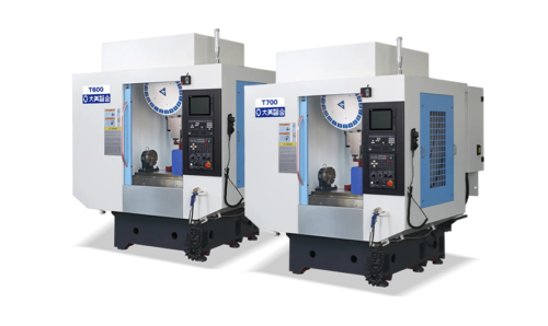
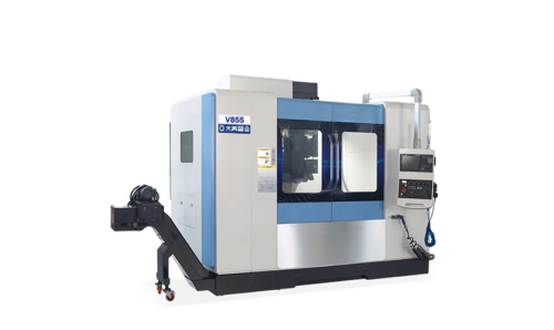
The primary difference lies in spindle orientation: VMCs feature a vertical spindle (Z-axis), whereas HMCs have a horizontal spindle. VMCs are well-suited for flat or shallow-cavity parts, as well as 2D/3D milling, drilling, and cavity machining; they offer simpler programming and workholding setups, along with excellent visibility for the operator. HMCs are better suited for parts requiring machining on multiple faces within a single setup; when paired with a rotary table, they can significantly boost spindle utilization (reaching up to 85% for HMCs, compared to an average of just 25% for VMCs). However, HMCs typically cost more than three times as much as VMCs and demand a higher level of technical expertise from operators. The choice should be based on part geometry, batch size, and the overall manufacturing strategy, rather than on any single specification.
Troubleshoot in the following order of priority:
① Excessive tool overhang—reducing overhang by 10% can increase rigidity by 25%; the tool extension length should not exceed three times its diameter;
② Insufficient chip load—excessive spindle speed or too low a feed rate causes the tool to "rub" or slip, leading to resonance; reduce speed or increase feed;
③ Tool wear—worn tools increase cutting forces; replace the tool promptly;
④ Toolpath type—traditional pocketing toolpaths cause sudden spikes in cutting force during directional changes; switch to constant-engagement toolpaths to eliminate load spikes;
⑤ Mismatch between tool diameter and corner radius—do not use a 0.5" tool to machine a 0.25" internal corner; select a smaller diameter tool instead;
⑥ Insufficient pull stud clamping force—spring fatigue can lead to loose tool clamping; measure the pull stud retention force.
External causes include insufficient tool rigidity or incorrect tool dimensions; internal causes may involve improper operation, incorrect cutting parameter settings, or uneven machining allowance leading to excessive tolerance deviations. Solutions include: ensuring uniform machining allowance and reserving sufficient stock for corner-clearing operations; using the largest possible tools; and utilizing the VMC's feed rate override (SF) function to fine-tune cutting performance and gradually identify the optimal cutting conditions.
Aside from operator error, common causes include burrs on the mold edges, sides that are not perpendicular, and a magnetized edge finder. Solutions include: demagnetizing the edge finder before use; performing double-checks during manual edge finding; maintaining the same height and position for the procedure; and periodically verifying the perpendicularity of the mold sides using a dial indicator.
Avoidable causes of collisions include: improper safety height settings; discrepancies between the tool length or machining depth listed on the tool setup sheet and the actual values; incorrect Z-axis coordinate settings; and improper coordinate system configuration during programming. Preventive measures include: accurately measuring the workpiece height and ensuring the safety height is set above the workpiece; ensuring the tools listed on the setup sheet match those actually used in the program (using setup sheets with images is recommended); carefully measuring the actual machining depth and clearly marking tool length and cutting edge length on the setup sheet; and double-checking Z-axis coordinate values.
The difficulty of 5-axis programming is often overstated, though the choice of control system does significantly impact the learning curve. Modern 5-axis control systems (such as Siemens SINUMERIK and Heidenhain TNC 640) feature built-in RTCP (Rotation Tool Center Point) and TRAORI (5-axis transformation) capabilities; this allows programmers to generate toolpaths using standard 3-axis logic, while the system automatically handles the necessary compensation calculations for the rotary axes. If your shop already uses CAM software like Mastercam, NX, or hyperMILL, 5-axis post-processors can usually be adapted directly. The real challenge lies not in the programming itself, but in understanding 5-axis kinematics—specifically, knowing when to use 3+2 positional machining versus full 5-axis simultaneous machining. It is recommended to start with 3+2 machining; it covers 80% of multi-sided machining requirements and is far less complex to program than full simultaneous 5-axis machining.
Small 5-axis machines typically accommodate workpieces within a 12-inch cube and weighing under 10 kg (though some compact models have even smaller rated working envelopes). However, this does not mean they are limited to "small parts"; because the rotary axes can reorient the workpiece, the effective machining range is far larger than the physical dimensions of the table. When purchasing, it is important to distinguish between three concepts: table diameter, workpiece swing diameter, and the tool's reach after axis rotation. The latter represents the true upper limit of machining capability. Additionally, small machine tools offer about 40% less chip clearance space than standard machines; chip management must be factored into the planning stage, as chip accumulation during machining can directly lead to precision issues and tool damage.
Investigate in the following order of priority:
① Thermal deformation—this accounts for 50%–70% of accuracy errors in 5-axis machining; accuracy is normal upon startup but drifts after hours of operation, usually due to spindle heat generation or ambient temperature fluctuations.
② RTCP/Rotation center calibration—offsets in the center position of the rotary axes cause tool center point errors; recalibration using a ballbar or specialized inspection tools is required.
③ Rotary axis backlash—measure using a dial indicator while rotating the A, B, or C axes in both directions; if backlash exceeds limits, the preload must be adjusted.
④ Parameter-mechanism mismatch—if alarms such as "No solution for tool orientation" or "5-axis axis configuration error" occur, verify that the 5-axis parameters match the machine's actual mechanical configuration.
⑤ Foundation installation—foundation settling or changes in levelness can affect both linear and rotary axes; re-verify installation accuracy using a precision level.
They do not necessarily possess "inherently higher" precision, yet in many scenarios, compact 5-axis machines can indeed achieve superior final accuracy. The key lies in the differences regarding error sources: while 3-axis machines primarily suffer from linear axis positioning deviations, and 5-axis machines introduce additional error terms from rotary axes, compact 5-axis machines benefit significantly from short travel distances. Shorter axis assemblies minimize the cumulative effects of thermal expansion and vibration—factors that are particularly critical for micron-level machining. Furthermore, the ability to machine multiple faces in a single setup eliminates cumulative positioning errors associated with repeated re-clamping; this factor often plays a more decisive role in final dimensional consistency than the machine's inherent geometric precision.

English

French

Portuguese

Spanish